21 Bit Protocol Scales
DRO-550 Cable Installation
DPU-550: PROCEED TO THE NEXT SECTION
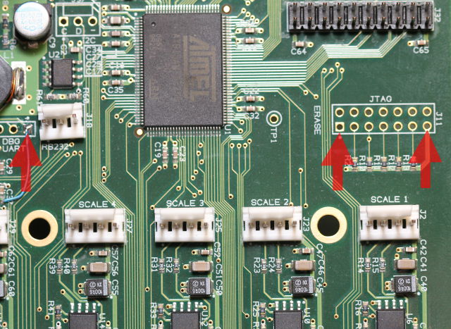
The iGaging scales need around 3V to operate. The DRO-550 scale interface was designed to operate at either 5V for quadrature scales or at 1.5V for Chinese scales. Thankfully, the DRO-550 processor uses 3.3V so we can supply the scales with that through the scale voltage selection jumper. In order to do that, we must find a suitable location to solder a one pin header so that we can jumper the 3.3V over to the scale interface. There are three 100 mil header locations on the DRO-550 that we can use to solder the one pin header included in the scale cable kit. Two of the locations are on the JTAG header J11 at pins 1 and 13. If you do not plan to develop software for the DRO-550, then the JTAG header on pin 1 is the best place and is what we will show. An alternative is on pin 1 of the UART debug header at J21. This is not the best location because it is the location that we use for the UART voltage rework but may be the only alternative if you plan to debug with JTAG.
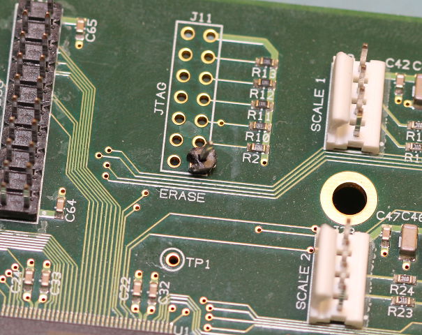
Once the location is selected, solder the one pin header into the hole from the back side of the DRO-550 PCB. You may want to remove the black key caps around the location of the hole so that you do not melt them with the soldering iron since they are spaced close together. Be careful when removing and reinstalling the key caps to avoid breaking the black tabs that hold them in place.
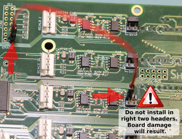
Now pick the scale input that you want to install the cable for. You can use any one of the five scale inputs you wish and there is no difference in using one over the other since they can be easily remapped to axes in OpenDRO's setup. Remove the black jumper from the scale voltage header for the scale input you selected. Use the red jumper and connect one side to the one pin header you installed in the previous step and the other end to one of the LEFT two pins on the scale voltage header. You can use the second pin on the left to daisy-chain to additional scale voltage headers if you want more than one iGaging scale on your system. Under any circumstance do not jumper onto the right two pins because that will short the power supplies together and bad things could happen.
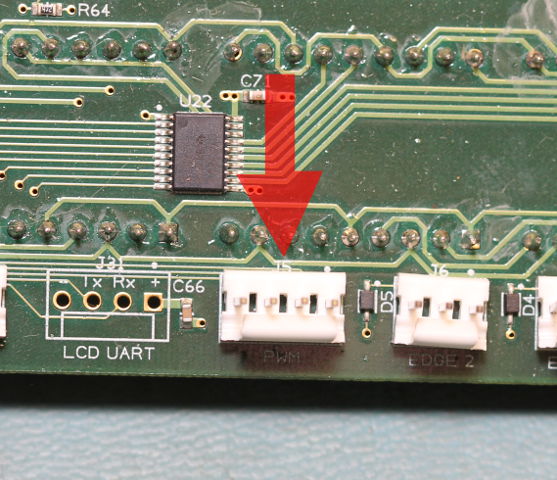
Take the four pin header included in the scale cable kit and solder it in place at position J5 in the lower right portion of the PCB. This position is also marked PWM underneath it. Hold the header with a finger and tack solder one pin to hold the header in place. Lay the board down and finish soldering the other three pins and return to the fourth pin you tack soldered to clean it up.
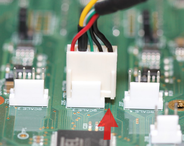
Now get the finished USB cable and install the five pin plug onto the four pin scale header. How do you install a five pin plug on a four pin header you ask? Easy, just hang the fifth pin with the cable shield over the side of the scale header. The cable shield is the black wire on one side of the plug. Take a look at the picture at left to confirm the orientation.
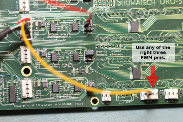
Plug the yellow jumper you soldered to the USB scale cable and install it any of the RIGHT three pins on the four pin header you previously soldered in place at J5. The left-most pin is a ground. OpenDRO generates a clock signal that is appropriate for the iGaging scales and outputs it on all three PWM outputs. Without this clock, the iGaging scales will not generate an output signal for the DRO to read.
The final step is to install the USB side of the cable on the back panel of the DRO-550. Pick any location you like as long as it is without obstructions underneath it and is close enough for the cable to reach the scale input. Drill a 5/8" (16mm) hole and install the scale cable by securing it with the plastic nut. The rubber O-ring goes on the outside underneath the lip of the connector to provide a seal.