DPU-550 Construction
Step 2. Disassemble the DRO-350
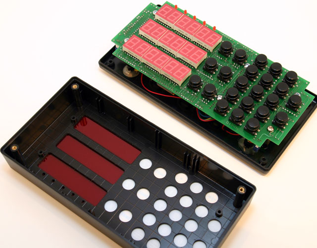 Remove all external cables and unmount the DRO-350 from your machine so that we can take it apart. Don't worry, it will be better than ever when we're done. Take it to a reasonably static-free workspace with your soldering equipment and tools handy. First, remove the four phillips head screws from the rear panel and carefully lift the front panel off. Set the front panel aside somewhere safe.
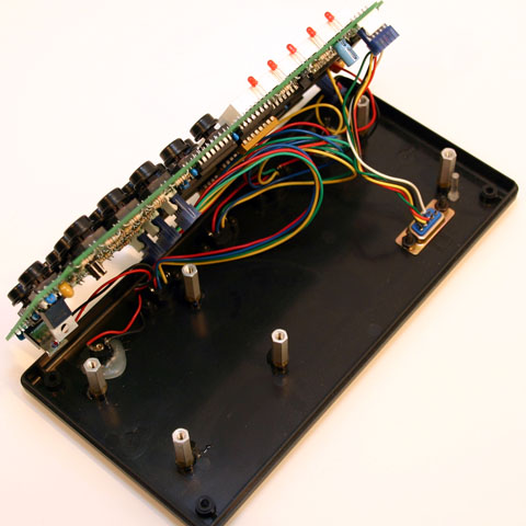 Place the DRO-350 back side down so that the PCB is facing up. Remove the six phillips head screws that attach the PCB to the standoffs and slowly lift the PCB up far enough so you can reach the headers that attach the external connectors to the PCB. Unplug all of the headers from the PCB and set the back cover to the side.
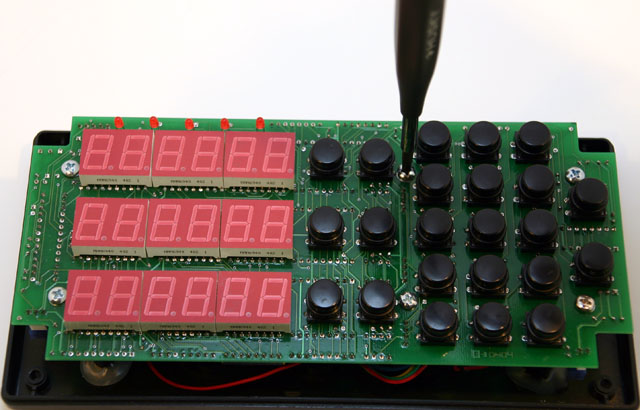
Set the DRO-350 PCB face down (the side with the LEDs) face down on your work surface. You might want to place a paper towel or other soft material between the PCB and your work surface so that it doesn't get scratched up. We are now ready for some surgery.