DPU-550 Construction
Step 5. Stick Rubber Feet On and Check Height
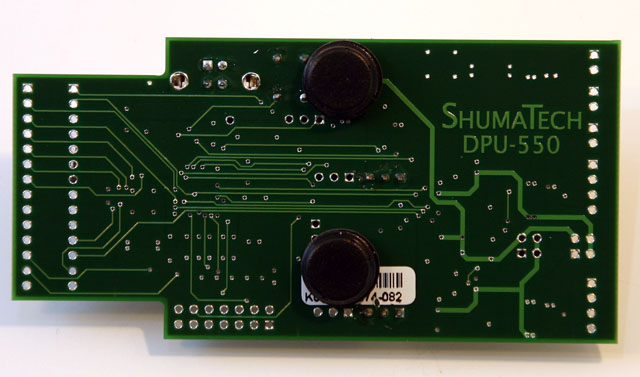
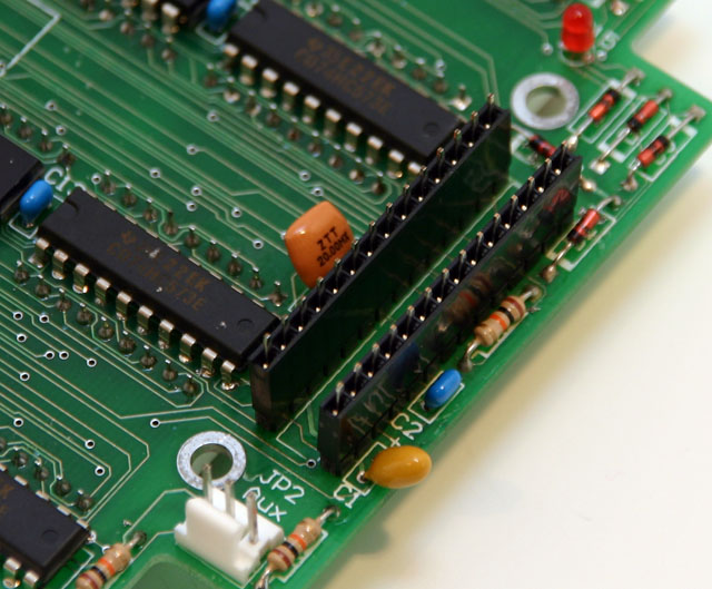
 We will now stick the rubber feet on the DPU-550 and check their mounting height. Remove the paper backing and stick them on to the positions shown in the picture. To check the height, we will push the two 14-pin female headers onto the two 14-pin male headers that we installed in the previous step. Once that is done, place the DPU-550 on top of the DRO-350 by slipping the metal tabs that stick out of the back of the two 14-pin female headers through the holes at positions J16 and J17 on the DPU-550.
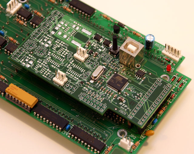
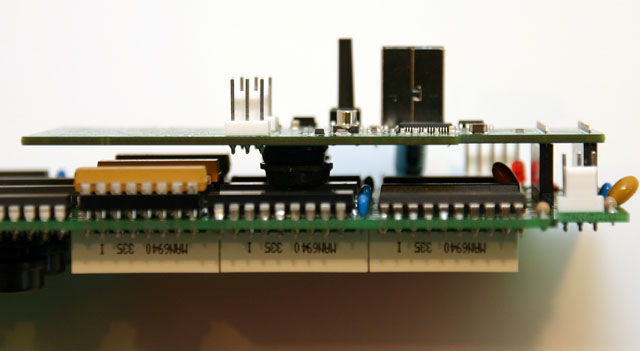 To check the mounting height, apply light pressure to the top of the DPU-550 near the J16 and J17 positions and view the two PCBs from the side. The DPU-550 should be parallel to the DRO-350. Don't worry if it's a tiny bit off but do get it fairly close. Since ICs vary in height and also because some people use sockets for their ICs, you may have to reduce the height of the feet. You can use sandpaper, an Xacto knife, or any other method you are comfortable with to remove a little bit of rubber from the feet. Recheck the mounting height and continue adjusting until the PCBs look parallel.