DRO-550 PCB Construction
Step 7. Solder LED Displays
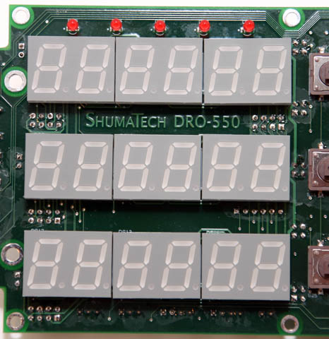
Install the nine 7-segment LED displays on the same side of the board as the keypad switches. One technique you can use is to lay the 7-segment display face down with the pins pointed up and then lay the board down on top of it by threading the pins through the appropriate holes in the board. Hold the board down against the display while you solder its pins. Be very careful to orient the 7-segment displays in the same direction with the decimal points oriented towards the lower right when viewed from the front. It is a lot of trouble to desolder a display if you get it wrong.
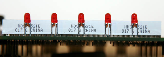
The five indicators LEDs are soldered into the DS1-DS5 positions above the 7-segment displays. Be careful to orient the LEDs properly into the holes. The SHORTER leg of the LED is inserted into the SQUARE pad on the board. If an LED doesn't work when you power up the board, then you probably inserted it backwards. Look at the picture at left to see the proper height at which to solder the LEDs. Don't worry if you don't get it perfect since the overlay will hide it. You can always go back and readjust the legs with the soldering iron if they are installed too tall or too short. After you are happy with their positions, clip the legs to a shorter length.