DRO-550 PCB Construction
Step 9. Board Rework
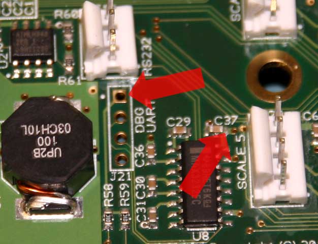
During testing, one minor problem was discovered with the production boards. The RS-232 transceiver is not reliably picking up 3.3V from the power plane underneath it. The power via is placed on the very edge of the plane and might not always touch it when tolerances are considered. The correction for this is easy and involves adding a wire to another 3.3V pad. If you are planning on using the RS-232 port, you should perform this rework.
Find the RS-232 circuit on the bottom left of the board as shown in the picture. The problem via is to the right of capacitor C37 and is highlighted by an arrow. The alternate 3.3V power to tap is pin 1 on J21 (DBG UART). Pin 1 is the square pad on top and is also highlighted with an arrow.
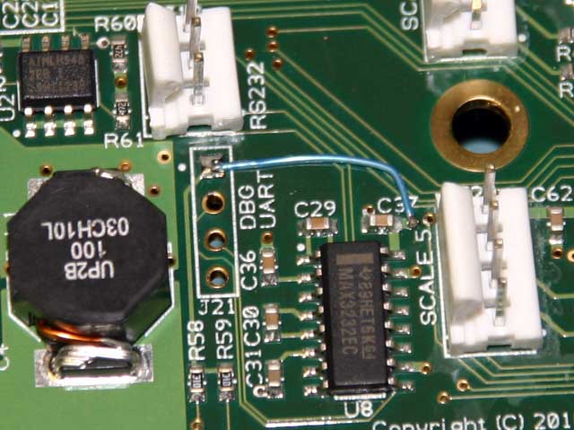
To affect the fix, solder a wire between the two locations. The C37-side of the wire can either be soldered on the via or on the side of the capacitor itself. The J21-side can be soldered anywhere on the square pad. That's all there is to it. Your RS-232 port is now good to go.