LCD-200 Construction
Step 2. Solder Semiconductors
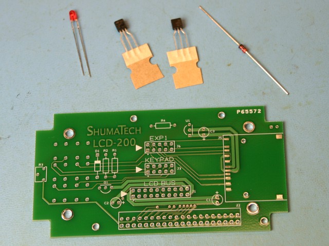
We will jump right in to soldering the board so get your soldering iron ready. Get the LCD-200 printed circuit board and parts bag #1 and dump its contents out. Make sure you are working on as static free a work surface as possible. Set the red LED aside since we will install it later once the LCD module is installed to assure proper mounting height.
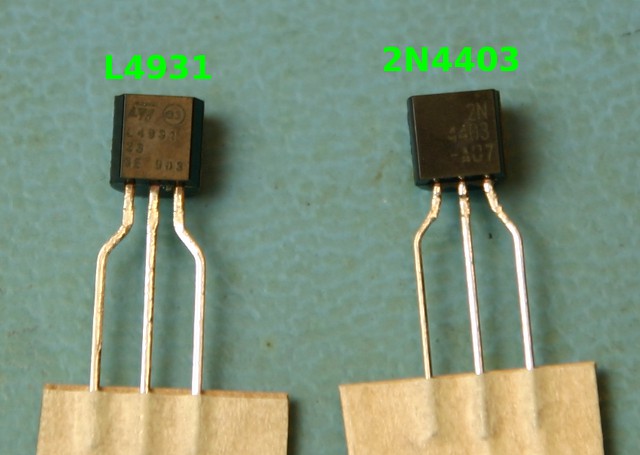
There are two black, three-legged parts that look identical but rest assured, they are not. We must first identify them to make sure we solder them into the correct positions. Look at the picture at left (click to enlarge) and you will see that one is a L4931 and the other is a 2N4403. If you have difficulty reading the writing on them, you can identify them by noticing that the 2N4403 has larger writing on the right side where the L4931 has smaller writing all over with a square and circle on top. Remove the L4931 from its cardboard tape and solder at position U1 on the upper right of the board. Notice that one side is round and the other is flat so make sure to install it with these surfaces matching the white silkscreen on the board. Do the exact same thing for the 2N4403 at position Q1 on the lower left.
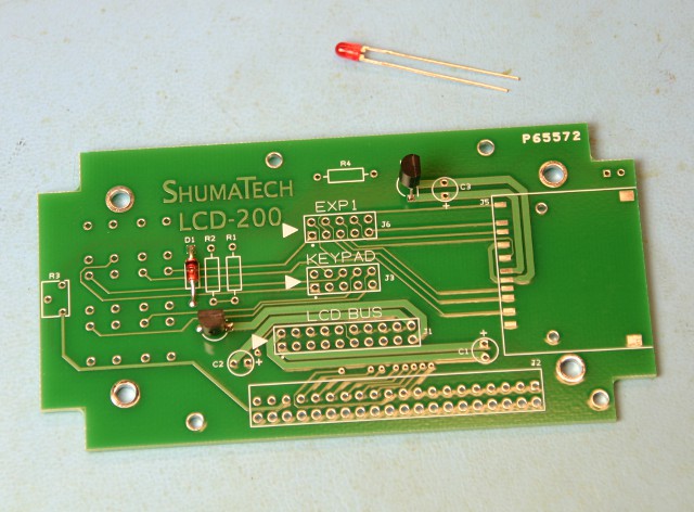
Retrieve the 1N4728 zener diode which is the part with a small orange body in the middle. It is mounted at position D1 on the left side of the board. Carefully bend the leads at right angles with a pair of plyers close to the diode body. Insert the leads into the holes making sure that the black ring on the diode body is oriented so it matches the direction of the white square on the silkscreen. When you are all done soldering, clip the leads fairly close to the board with a pair of diagonal cutters.