LCD-200 Construction
Step 4. Solder Passive Components
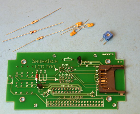
We are now ready to solder the passive components (resistors and capacitors) so dump parts bag #3 out on your work surface. The first step is to identify and solder the resistors in place. The first resistor is a 10K ohm which has brown-black-orange bands around its body. Bend its leads like you did for the zener diode and solder it in position R1. The 1K ohm resistor has brown-black-red bands and is installed in position R2 next to R1. The last resistor is a 560 ohm which has green-blue-brown bands. Install it in position R4 near the top of the board and solder it in place. The blue cube is a potentiometer that sets the LCD display's contrast. Solder it at position R3 on the left side of the board.
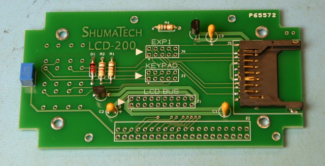
The three capacitors are installed next. The capacitors are all identical so don't worry which one you solder in a position. Newer kits come with BLUE ceramic capacitors that are NOT polarized so you can solder them in any orientation. Older kits come with YELLOW tantalum capacitors that ARE polarized so it is very critical to solder them in the correct orientation to prevent the release of magic smoke. For the YELLOW capacitors, look at the capacitor and notice that there is a vertical line that ends in a + symbol that is closer to one lead than it is the other and that the lead is slightly longer than the other lead. That designates the positive lead of the capacitor. You MUST solder each YELLOW capacitor so that the positive lead matches up with the white + symbol printed on the board. Solder the capacitors at each position C1 on the lower right, C2 on the lower left, and C3 on the upper right. When you are all done soldering, clip the leads fairly close to the board with a pair of diagonal cutters.