LCD-200 Construction
Step 7. Mount the LCD
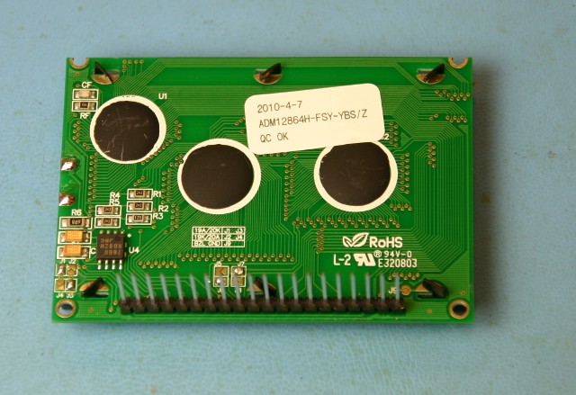
Solder the 20 pin header on the back side of the LCD which is the side opposite the display with the three black domes. The short pins poke through the holes to the front side and the long pins stick out. Solder the pins from the front side being careful to make sure that the black plastic retaining strip is flush against the LCD and also that the pins stay as perpendicular as possible to the LCD module. It may help to solder only one pin from the front side and then flip the LCD over to check the fit. That will make it easier to adjust the header if it's not quite right by simply reheating the one pin. Once you have a good, perpendicular fit, solder the rest of the pins.
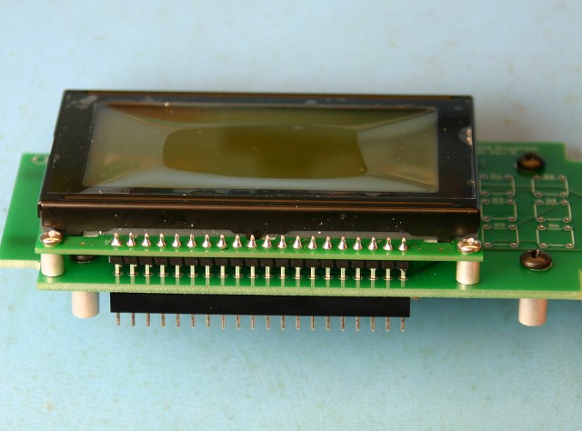
Mount the LCD module on the LCD-200 board by inserting the 20 pin header through the holes on the board until the LCD module sits flush on the standoffs and the 20 pin header pokes through the MDF7 header at position J2. Secure the LCD module by using the two remaining 2-56 x 1/8" screws on each side of the 20 pin header.