DRO-350 Cables Construction
Scale Cables

If you can handle basic soldering, it is easy to build cables for the Chinese scales yourself. In some respects, I would almost recommend it over buying the commercial cables. The big problem with the commercial cables is that the end that plugs into the scale is poorly designed. It can be difficult to get a good connection without a lot of fidgeting with the connector. Also, the connector sometimes has a tendency to short across the pads which will either prevent the DRO-350 from reading the scale or even cause the DRO-350 to shut down power to the scales if the positive supply is shorted.
To make your own cables you need to buy four pin mini-DIN plugs. PS/2 keyboard and mouse plugs are mini-DIN as well, the only difference being that they have six pins instead of the four used by the DRO-350. Mouser carries these plugs, stock no. 171-2604, for a reasonable price. You can also check the other electronics distributors such as Digi-Key, Allied, Newark, etc. I would recommend the "solder cup" style over the "solder posts" style because they are easier to solder. The cable connecting the mini-DIN plug to the scale is not critical, just keep the length short. You can use whatever cable you have lying around.

The Chinese scale side of the cable is just a little more difficult. I know of no off-the-shelf plugs that work with the jack on these scales. The jack on the scale is basically just four pads on a PCB. Even if the plugs were available, I would still recommend you do the following to get a solid, reliable connection.
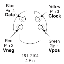
The pin-out for the DRO-350 female mini-DIN jack is shown to the left. The plug is male and engages into the jack. Just imagine sticking the plug into the screen and you will get the pin-out right. Solder the cable to the four cups/posts and reassemble the plug.
What I recommend is to solder the four wires from the cable directly onto the pads on the scale. Start by tinning the four pads with solder. You don't want a big puddle of solder but you do want enough to make a solid connection to the wire on the cables. Next, strip the end of each wire and attach it to each pad by holding the wire against the pad with one hand and touching the pad with the solder iron with the other hand. Look at the diagram of the scale jack below to figure out which wire to solder to which pad. The most important thing here is to hold the wire and scale as steady as possible so that you get a good, strong solder joint.
To cover the jack, you can cut a small notch in the little plastic cover for the jack and route the wires through it. I will post pictures of everything I have described as soon as time allows.
- « first
- ‹ previous
- 1
- 2
- 3
