DRO-350 PCB Construction
 |
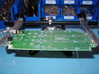
Step 3. Install the Decoupling CapacitorsBefore installing any ICs, it is easiest to install the decoupling capacitors first. All the decoupling capacitors are 0.1uF ceramics and do NOT have polarity so you can solder them in any orientation. The decoupling capacitors have designators C2, C8, C9, C10, C11, C12, C13, C14, C16, and C17. There is a 10uF tantalum capacitor next to the PIC with designator C1. This capacitor provides filtering for the PIC since it is several inches away from the 5V power supply. This capacitor is polarized so solder it in place as described previously for the tantalum capacitors in the power supplies. Insert all of the indicated capacitors and spread their leads apart as before. Solder them in place from the display side. Use diagonal cutters to clip all of the leads. |
