DRO-375 PCB Construction
Step 2. Visual Inspection
The DRO-375 circuit board is professionally manufactured on a modern surface mount assembly line. The boards go through automated inspection to verify the manufacturing process but there is always the possibility that an undetected flaw passes through. The incidence of these flaws is extremely low but it only takes a couple of minutes to check for the most likely failure points before applying power and doing permanent damage to the board.
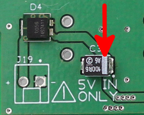
First, we visually inspect the power input for components installed with an incorrect orientation. Reference the picture on the left. The red arrows point out the orientation marks for components that must be placed on the board in a certain way. The orientation marks are small lines or dots that are marked on the components. There are also small white dots on the printed circuit board that indicate the correct position of the orientation marks with respect to the board. For each red arrow in the picture, make sure that the component's orientation mark exactly matches the position as shown in the picture.
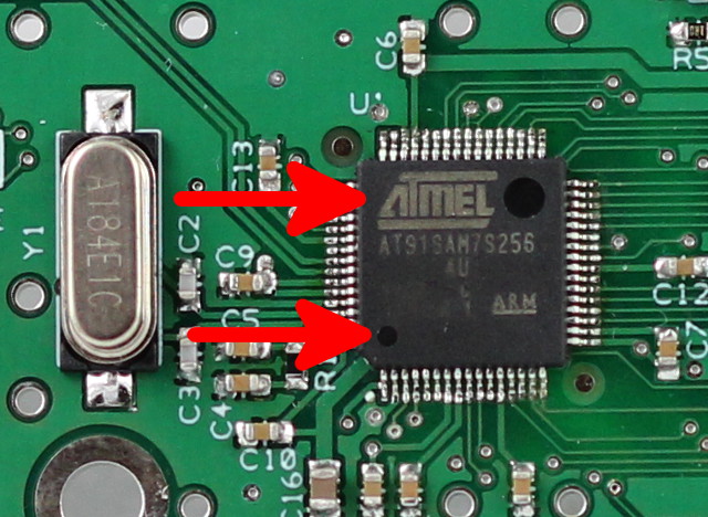
Next, check the ARM7 processor in the middle-left side of the board. It is the largest device and says "Atmel" in large lettering. Check that the direction of the lettering matches the picture at left. You can also note that the orientation dot is in the lower, left-hand side on the processor.
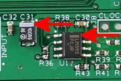
There are three identical scale interfaces that are organized in rows down the middle of the board. Check each scale interface for the three orientations noted in the picture at left.
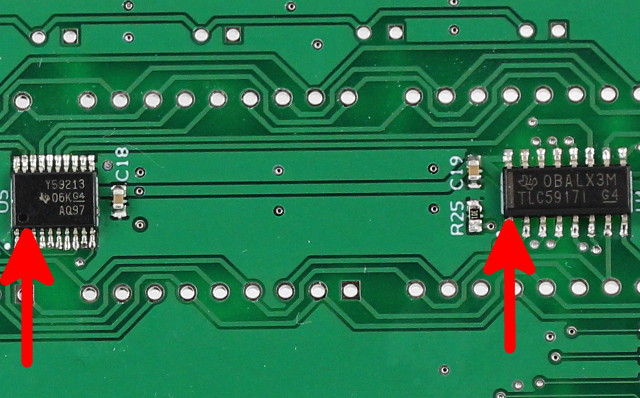
Visually check the orientations of the display drivers. There are two ICs for each of the three display rows and they are located on the right side of the board. The left IC is the column driver and it should have its orientation mark in the lower left. The right IC is the segment driver for the row and its orientation mark should be to the lower left.
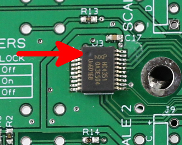
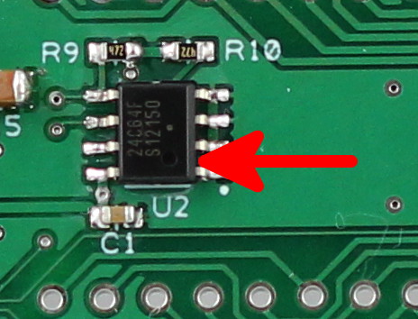
Lastly, check the scale switch and EEPROM devices as shown in the pictures. The scale switch orientation is to the upper left and the EEPROM orientation is to the lower right.
If any of the orientations described above are not correct, then DO NOT POWER ON THE BOARD!!!! You will likely damage the component and possibly even the power supply. Instead, desolder the device and reinstall it with the correct orientation. If you are not sure how to desolder the component, then contact us at ShumaTech or seek advice on the ShumaTech message board.