DRO-375 PCB Construction
Step 6. Solder Piezo Speaker
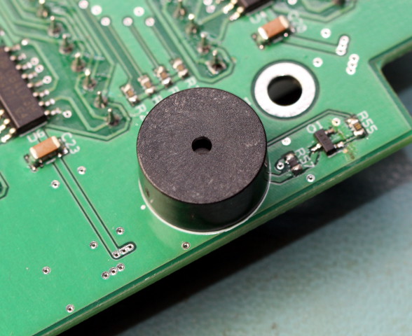
Solder the piezo buzzer into position onto the side of the board. There is room to solder it either on the component side or the display side of the board. A little experimentation might be necessary to refine the volume to your liking. You can also partially cover the small hole on top with tape to make it quieter.
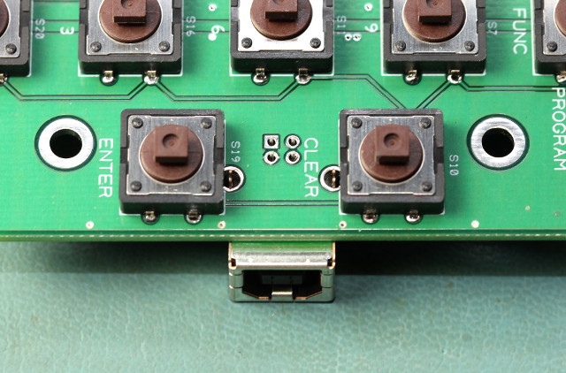
The USB connector is inserted onto the component side of the board. Push the four pins and two mounting tabs through the holes. The mounting tabs should just miss the 12mm tact switches on the opposite side of the board. Press down on the board while soldering the four pins to assure that the connector sits flush on the board. Also solder the two mounting tabs to give the connector extra support when inserting and removing the USB cable.