DPU-550 Construction
Step 1. Complete DPU-550 Assembly
Depending on which DPU-550 product you ordered and what parts were included with it, you might need to finish assembling your DPU-550. At a minimum the basic ARM processor circuit is complete and ready for use. However, you might have to install through-hole connectors and jacks which will require basic soldering skills. Review the material on static protection and soldering on the DRO-350 PCB construction page if you need a refresher before you begin.

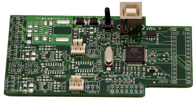 The DPU-550 Lite variant is a common product configuration and we will cover its assembly here. The Lite variant consists of the ARM7 processor without the RS-232 interface, 5V power supply, and the two extra scale interfaces. The first step is to install the two white, 3-pin, MTA headers in positions J2 and J3 in the middle of the DPU-550. The best technique to solder them is to place one at a time into position, hold it there with the tip of your fingernail, flip the PCB over to the back side (the side with ShumaTech DPU-550 lettering), and use your work surface to hold in place as you solder.
Once you are done with those, you should install the USB type B plug at position J5 in the upper right corner of the PCB. Line up the pins and the tabs and carefully push it through the holes until it reaches bottom. Solder it in place from the back side.
Lastly, push the tact switch through the holes at position S1 just to the left of the USB plug. Make sure it reaches the bottom and solder it into position from the back. Check to make sure that bottoms of the tact switch and USB plug are in contact with the PCB or it will be harder to close the case later on.
Do NOT solder the two 14-pin male headers and the two 14-pin female headers. We will solder them in place during a later step in construction.
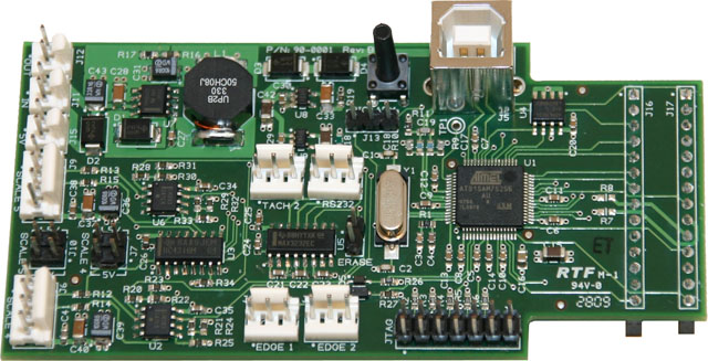 Your DPU-550 Lite is now ready for installation. If you are interested in increasing the capabilities of your DPU-550 Lite and can handle surface mount soldering, then you can acquire the required parts listed in the Bill of Materials and do the assembly yourself. We will not cover that here since if you are comfortable surface mount soldering, then you will know how to finish the assembly. One thing to note is that if you add the 5V power supply to the DPU-550 Lite, then you should remove resistors R7 and R8 next to the PIC header since you will not need 5V power from the DRO-350 anymore.