LCD-200 Construction
Step 14. Solder DRO-550 Headers
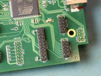
In step 5, we set aside two 2x5 pin headers and one 2x10 pin header. We will now solder those in place on the DRO-550 board. If you already have your DRO-550 board installed in its case, you will have to remove it before we begin. The 2x10 pin header is placed in position 20 with the label LCD BUS. The two 2x5 pin headers are placed in position J20 with label EXP1 and J1 with label KEYPAD. Note that the pads on the PCB are 2x6 instead of 2x5 like the headers. You must place the headers as shown in the picture skipping the row with the square pad with the white dot next to it. Why? Because those signals are not used by the LCD-200 and 12 pin ribbon cable assemblies are very difficult to find.
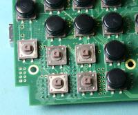
Before soldering you should remove the black key caps as shown in the picture as carefully as possible. This is to keep from melting them with the soldering iron and causing a sharp edge that might wear the overlay. Don't worry if you accidentally melt the brown switch bodies a bit since it is unlikely you'll do any real damage. Solder each header in place in turn and put the black key caps back on when you are done.