LCD-200 Construction
Step 15. Reassemble the DRO-550
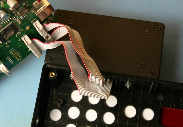
We are now ready to complete the LCD-200 installation by connecting the ribbon cables to the DRO-550 and reinstalling the DRO-550 board and case back. First, remove the DRO-550 board from the case back to give you room to work. Next, plug the 2x5 ribbon cable on top into J20 with label EXP1. Make sure that the red edge of the ribbon cable points toward the processor as shown in the picture. The ribbon cable in the middle is also a 2x5 and it plugs into J1 with label KEYPAD. It is also installed so the red edge of the ribbon cable points towards the processor. The last ribbon cable is a 2x10 that is installed in J32 with label LCD BUS. It is also installed with the red edge towards the processor.
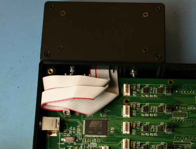
Reinstall the DRO-550 board on the case back. You will have to move the ribbon cables a little bit to make room for the standoff. You can also leave that standoff off the DRO-550 since the five standoffs left will give the DRO-550 board plenty of support. The picture shows how the ribbon cables should be routed to keep them out of the way. Note that the picture does not show the DRO-550 case back for clarity. Once you have the case back on, reattach it with the screws and you are done with the installation.